
Introduction
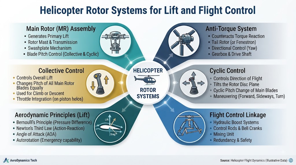
Helicopter rotor systems are among the most important engineering systems in rotorcraft because they provide the aerodynamic forces required for flight and maneuvering. Unlike fixed-wing aircraft, helicopters rely heavily on rotating airfoils to generate lift and control movement. The main rotor, swashplate, rotor mast, hub, blades, transmission, and flight-control system work together as an integrated assembly. A helicopter may also use a conventional tail rotor or another anti-torque system to manage yaw and compensate for main rotor torque. Understanding these components helps pilots, aircraft owners, aviation students, and enthusiasts better appreciate how helicopters hover, climb, descend, turn, and fly forward. Because rotor systems vary considerably between helicopter designs, aircraft-specific manuals and qualified professionals remain essential for operational and maintenance decisions.
What Is a Helicopter Rotor System?
A helicopter rotor system is the rotating aerodynamic and mechanical assembly that generates the forces needed for helicopter flight.
A typical rotor system can include:
- Rotor blades
- Rotor hub
- Blade grips
- Rotor mast
- Swashplate
- Pitch-change mechanisms
- Bearings and linkages
- Transmission
- Drive system
- Anti-torque components
The engine provides power to the drivetrain, while the transmission transfers that power to the rotor system.
The pilot then uses flight controls to influence rotor blade pitch and rotor disc orientation.
This coordinated system allows a helicopter to:
- Hover
- Climb
- Descend
- Move forward
- Move backward
- Move laterally
- Control yaw
- Maneuver in different flight conditions
The exact configuration depends on the helicopter’s design.
How Helicopter Rotor Blades Generate Lift
Helicopter rotor blades function as rotating airfoils.
As the blades rotate, they move through the surrounding air and generate aerodynamic forces. Blade pitch and airflow conditions influence the amount and direction of those forces.
Important aerodynamic concepts include:
- Airflow
- Blade pitch
- Angle of attack
- Relative wind
- Lift
- Drag
- Rotor speed
The rotor disc can be thought of as the circular area swept by the rotating blades.
By changing blade pitch and the orientation of the rotor disc, the helicopter can control the direction and magnitude of rotor-generated forces.
This is one of the fundamental differences between helicopters and conventional fixed-wing aircraft.
Main Rotor System
The main rotor is the primary aerodynamic system on most helicopters.
Its major functions include:
- Generating lift
- Supporting hover
- Producing thrust for forward flight
- Contributing to climbing and descending
- Allowing directional maneuvering
The main rotor does not simply spin at a fixed configuration while the aircraft moves around it.
The rotor system is continuously influenced by pilot inputs and aerodynamic conditions.
Changes in blade pitch and rotor disc orientation allow the helicopter to redirect rotor-generated forces.
Major Main Rotor Components
Rotor Blades
Rotor blades are rotating airfoils designed to generate aerodynamic forces.
Depending on the helicopter, blades can be manufactured using materials such as:
- Aluminum alloys
- Composite materials
- Specialized metal structures
- Other engineered materials
Modern composite construction is used extensively in many rotorcraft designs, although traditional metal and other construction methods remain relevant.
Rotor blades must withstand substantial aerodynamic and mechanical loads.
Areas of concern can include:
- Leading-edge erosion
- Surface damage
- Cracks
- Corrosion
- Tip damage
- Impact damage
- Delamination where applicable
The significance of any damage depends on the specific blade design and manufacturer’s requirements.
Rotor Hub
The rotor hub connects the blades to the rotor mast.
Depending on the rotor configuration, the hub allows the blades to perform the movements required for flight control and aerodynamic load management.
Rotor hubs can have substantially different designs.
Some systems incorporate articulated movement, while others use different mechanical arrangements to achieve required blade motion.
Rotor Mast
The rotor mast provides the mechanical connection between the transmission and rotor assembly.
It transfers rotational movement from the drivetrain to the rotor system.
Because the mast is part of the primary power path, its design and condition are important to helicopter operation.
Blade Grips
Blade grips connect individual blades to the rotor hub.
They can also form part of the mechanism through which blade pitch is controlled.
Their exact design depends on the rotor system.
Bearings and Bushings
Some rotor systems incorporate bearings and bushings to support controlled mechanical movement.
These components can reduce friction and help associated parts move within their designed ranges.
Their inspection and replacement requirements are specific to the helicopter and component design.
Helicopter Swashplate System
The swashplate is one of the most important components in conventional helicopter flight control.
Its primary purpose is to transfer stationary pilot control inputs to rotating rotor components.
The system allows pilot commands to influence blade pitch while the rotor continues rotating.
The swashplate is associated primarily with two important forms of control:
- Collective pitch
- Cyclic pitch
Understanding these two functions makes helicopter flight control much easier to understand.
Collective Control
Collective control changes the pitch of the main rotor blades together.
When collective pitch changes, the aerodynamic forces produced by the rotor also change.
This influences the helicopter’s vertical movement.
In simple terms:
Collective → Overall blade pitch → Rotor thrust → Vertical movement
Collective control is therefore strongly associated with:
- Hovering
- Climbing
- Descending
However, changing collective also affects engine and rotor-system power requirements.
The precise control response depends on the helicopter’s design and operating condition.
Cyclic Control
Cyclic control changes blade pitch according to the blade’s position around the rotor’s rotation.
Rather than changing all blades equally at the same instant, cyclic control creates a changing pitch pattern as the blades rotate.
This causes the rotor disc to tilt.
The resulting change in the direction of rotor-generated force allows the helicopter to move:
- Forward
- Backward
- Left
- Right
A simple conceptual relationship is:
Cyclic input → Changing blade pitch → Rotor disc tilt → Directional movement
This is a fundamental principle behind helicopter maneuvering.
Pedal Control and Anti-Torque
A conventional helicopter’s main rotor creates torque as it rotates.
That torque can cause the helicopter fuselage to rotate in the opposite direction if it is not counteracted.
An anti-torque system helps manage this reaction.
In conventional helicopters, the tail rotor provides the required counteracting force.
Pedal controls allow the pilot to influence tail rotor blade pitch and therefore control yaw.
This gives the pilot directional control around the helicopter’s vertical axis.
Not all helicopters use a conventional tail rotor, however.
Tail Rotor System
The tail rotor is an important component of many conventional helicopter designs.
A typical tail rotor system can include:
- Tail rotor blades
- Tail rotor hub
- Pitch-control mechanism
- Drive shaft
- Gearbox
- Supporting structure
The tail rotor generates a sideways aerodynamic force that helps counteract main rotor torque.
Changing tail rotor blade pitch changes the amount of anti-torque force.
This allows the pilot to control yaw.
The tail rotor therefore serves a different primary function from the main rotor.
The main rotor is primarily responsible for lift and major directional force, while the conventional tail rotor primarily provides anti-torque and yaw control.
Alternative Anti-Torque Systems
Not every helicopter uses a conventional tail rotor.
Some rotorcraft use alternative technologies.
Fenestron-Type Systems
A Fenestron-type system places multiple smaller rotor blades inside a shrouded housing.
The system performs the anti-torque function while using a different aerodynamic and structural arrangement from an exposed tail rotor.
NOTAR-Type Systems
NOTAR systems use an alternative anti-torque concept involving controlled airflow rather than a conventional exposed tail rotor.
These designs demonstrate that helicopter engineers can solve the torque-control problem in different ways.
The exact characteristics and performance of each system depend on the helicopter’s engineering design.
Rotor Configurations
Helicopters can use several different rotor arrangements.
Single Main Rotor
This is one of the most familiar helicopter configurations.
It generally includes:
- One primary main rotor
- A tail rotor or alternative anti-torque system
The main rotor provides lift and directional force while the anti-torque system manages yaw.
Tandem Rotor
Tandem rotor helicopters use two main rotor systems positioned at different locations along the aircraft.
The rotors generally rotate in opposite directions to balance torque.
This configuration can provide significant lifting capability while eliminating the need for a conventional tail rotor.
Coaxial Rotor
Coaxial helicopters use two rotors mounted around the same central axis.
The rotors rotate in opposite directions.
This arrangement allows the torque effects of the two rotor systems to counteract one another.
Intermeshing Rotor
Intermeshing rotor systems use two rotor assemblies positioned at an angle so that their blades occupy overlapping areas without colliding.
The rotors rotate in opposite directions.
This arrangement provides another method of balancing torque without a conventional tail rotor.
Compound Rotorcraft
Compound rotorcraft combine a main rotor system with additional propulsion or aerodynamic systems.
The objective is to supplement the capabilities of the rotor system under appropriate flight conditions.
The exact configuration varies by aircraft.
Rotor RPM
Rotor RPM is an important factor in helicopter flight.
Rotor blades are designed to operate within specific aerodynamic and mechanical ranges.
Rotor speed affects:
- Aerodynamic performance
- Lift generation
- Blade airflow
- Engine power requirements
- Rotor control
- Aircraft behavior
Helicopter designs therefore have specific rotor operating limitations.
Pilots and maintenance personnel must follow the applicable aircraft documentation rather than relying on generic RPM values.
Blade Pitch and Rotor Performance
Blade pitch refers broadly to the orientation of a rotor blade relative to the plane of rotation.
Changing blade pitch influences aerodynamic forces.
Three important concepts are:
Collective Pitch
Changes the overall pitch of the rotor blades.
Cyclic Pitch
Changes blade pitch according to rotor position.
Feathering
Refers to rotation of an individual blade around its longitudinal axis to change pitch.
These concepts work together to provide helicopter flight control.
Dissymmetry of Lift
One of the important aerodynamic challenges in helicopter flight is dissymmetry of lift.
During forward flight, the advancing blade moves through the air at a different relative speed from the retreating blade.
This creates differences in aerodynamic conditions across the rotor disc.
Without appropriate aerodynamic compensation, these differences could create significant control problems.
Helicopter rotor systems use blade movement and pitch changes to manage these effects.
Important rotor movements include:
- Flapping
- Feathering
- Lead-lag movement where applicable
These movements allow the rotor system to respond to changing aerodynamic loads.
Blade Flapping, Feathering, and Lead-Lag
Flapping
Flapping refers to upward and downward movement of rotor blades.
It can help manage differences in aerodynamic forces experienced by the blades.
Feathering
Feathering involves changing the blade’s pitch by rotating it around its longitudinal axis.
This is fundamental to both collective and cyclic pitch control.
Lead-Lag
Lead-lag movement refers to controlled fore-and-aft blade movement in rotor systems designed to accommodate this type of motion.
Not every helicopter uses the same lead-lag arrangement.
The exact mechanism depends on rotor design.
Rotor Transmission and Power Flow
The engine does not normally connect directly to the main rotor.
Power is transferred through the helicopter’s drivetrain.
A simplified power path is:
Engine → Transmission → Rotor Mast → Main Rotor
For helicopters with conventional tail rotors, another power path may extend through:
Transmission → Drive Shaft → Tail Gearbox → Tail Rotor
The transmission performs an important role in transferring and managing engine power for the rotor system.
Depending on the helicopter, the drivetrain may include:
- Main transmission
- Drive shafts
- Gearboxes
- Rotor mast
- Tail rotor gearbox
- Associated couplings and mechanical components
The exact arrangement varies between helicopter designs.
Helicopter Flight Controls
| Control | Primary Function | Main System Affected |
|---|---|---|
| Collective | Changes overall rotor blade pitch | Main rotor |
| Cyclic | Changes rotor disc orientation | Main rotor |
| Pedals | Controls yaw | Anti-torque system |
| Power control | Manages available engine/rotor power depending on design | Engine and drivetrain |
These controls work together rather than independently.
For example, changing collective can affect power requirements, while cyclic movement changes the direction of rotor-generated force.
The pilot must therefore manage the helicopter as an integrated system.
Rotor System and Helicopter Flight
Hovering
During a hover, the main rotor produces enough upward aerodynamic force to counteract the helicopter’s weight.
The rotor disc remains generally above the aircraft while the helicopter maintains its position relative to the surrounding environment.
Hovering requires continuous control because wind and other aerodynamic factors can influence the aircraft.
Climbing
A climb occurs when the helicopter develops sufficient upward force relative to its weight and operating condition.
Collective control plays an important role in changing rotor thrust.
Descending
During descent, the relationship between rotor thrust, aircraft weight, airflow, and power changes.
Different descent conditions can create different aerodynamic effects.
Forward Flight
Cyclic control changes the orientation of the rotor disc.
This redirects part of the rotor-generated force horizontally, allowing the helicopter to accelerate forward.
Turning
Helicopter turning involves coordinated use of the rotor system and directional controls.
The exact control response depends on the helicopter’s configuration and flight condition.
Autorotation
Autorotation is a flight condition in which the rotor continues to rotate primarily because of aerodynamic airflow through the rotor system rather than normal powered drive from the engine.
It is an essential concept in helicopter training and emergency aviation knowledge.
During autorotation, airflow through the rotor can provide the aerodynamic energy necessary to maintain rotor rotation.
Several factors become important, including:
- Rotor RPM
- Airspeed
- Blade pitch
- Aircraft energy
- Descent rate
Autorotation procedures are aircraft-specific.
Pilots should learn and practice them through qualified flight instruction using the applicable helicopter’s approved flight manual and training procedures.
Generic emergency instructions should never replace aircraft-specific training.
Common Rotor System Issues
Rotor systems operate under significant aerodynamic and mechanical loads.
Potential concerns can include:
- Excessive vibration
- Blade damage
- Corrosion
- Unusual noise
- Control-system wear
- Transmission concerns
- Drive-system problems
- Tail rotor issues
- Bearing problems
- Lubrication concerns where applicable
A particular symptom does not necessarily identify a single component as the cause.
For example, unusual vibration could originate from the rotor system, drivetrain, engine, transmission, tail rotor, or other aircraft components.
Professional diagnosis is therefore important.
Rotor Vibration
Vibration deserves particular attention in rotorcraft.
Possible sources include:
- Rotor blade condition
- Rotor balance
- Hub components
- Bearings
- Drive system
- Transmission
- Engine
- Tail rotor
- Airframe components
Not every vibration indicates the same type of problem.
A change from an aircraft’s normal vibration characteristics should be appropriately evaluated rather than dismissed.
Qualified maintenance professionals can use aircraft-specific procedures and equipment to identify potential sources.
Rotor System Maintenance
Rotor systems require disciplined maintenance because their components experience substantial aerodynamic and mechanical forces.
Maintenance planning may involve:
- Manufacturer documentation
- Scheduled inspections
- Service information
- Component life limitations where applicable
- Approved replacement parts
- Maintenance records
- Qualified maintenance personnel
Maintenance requirements differ significantly between helicopters.
Owners and operators should therefore avoid applying generic inspection intervals or procedures to a specific aircraft.
The helicopter manufacturer’s approved documentation should remain the primary technical reference.
Rotor System Safety Considerations
Rotorcraft introduce hazards that are different from many fixed-wing aircraft.
Important safety considerations include:
- Rotor awareness
- Ground personnel awareness
- Rotating components
- Blade clearance
- Foreign-object damage
- Maintenance hazards
- Weather conditions
- Safe aircraft positioning
- Proper maintenance procedures
A helicopter’s rotor blades can create significant hazards even when the aircraft is operating in seemingly routine conditions.
Pilots, passengers, ground crews, and maintenance personnel should follow established safety procedures and receive appropriate training.
Main Rotor vs Tail Rotor
| Feature | Main Rotor | Tail Rotor/Anti-Torque System |
|---|---|---|
| Primary role | Lift and directional force | Yaw and anti-torque control |
| Location | Main rotor area | Usually tail area in conventional designs |
| Pilot control | Collective and cyclic | Pedals in conventional systems |
| Blade pitch | Changes through flight controls | Changes for yaw control |
| Hover function | Produces primary lift | Helps counter main rotor torque |
| Forward-flight role | Lift and propulsion | Directional control |
Alternative rotorcraft configurations can use different arrangements.
Common Misconceptions About Helicopter Rotor Systems
1. Helicopter Blades Simply Spin Without Changing Pitch
Rotor blade pitch changes are fundamental to helicopter control.
Collective and cyclic inputs influence blade pitch in different ways.
2. The Tail Rotor Is Only Used During Turns
The conventional tail rotor primarily provides anti-torque and yaw control.
Its function is not limited to turning the helicopter.
3. Every Helicopter Uses a Tail Rotor
Several helicopter configurations use alternative anti-torque arrangements, including coaxial, tandem, intermeshing, and other systems.
4. The Main Rotor Only Produces Vertical Lift
The main rotor can redirect its aerodynamic force to support forward, backward, or lateral movement.
5. Rotor RPM Is Unimportant If the Engine Is Running
Rotor RPM is an important aspect of helicopter operation.
The rotor must operate within the limits established for the specific aircraft.
6. All Helicopters Use the Same Swashplate
Swashplate designs and rotor-control arrangements vary between helicopters.
7. Composite Rotor Blades Require No Maintenance
Composite construction does not eliminate inspection and maintenance requirements.
8. A Small Amount of Vibration Is Always Normal
Helicopters naturally have different vibration characteristics from fixed-wing aircraft, but changes or unusual vibration should not automatically be dismissed.
Rotor System Inspection Awareness Checklist
A general awareness checklist can include:
- Rotor blade condition
- Blade tips
- Leading edges
- Rotor hub
- Blade attachment areas
- Swashplate
- Control linkages
- Bearings where applicable
- Rotor mast
- Transmission
- Tail rotor
- Drive shafts
- Gearboxes
- Anti-torque system
- Vibration observations
- Maintenance records
- Applicable service information
This is an awareness checklist, not an approved maintenance inspection.
Actual inspections must follow the applicable helicopter manufacturer’s procedures and regulatory requirements.
Rotor System Comparison
| Rotor Configuration | Main Characteristic | Anti-Torque Arrangement |
|---|---|---|
| Single main rotor | One primary rotor | Tail rotor or alternative system |
| Tandem rotor | Two main rotors | Torque balanced by rotor arrangement |
| Coaxial rotor | Two counter-rotating rotors on one axis | Torque balanced by opposing rotors |
| Intermeshing rotor | Intersecting counter-rotating rotors | Torque balanced through rotor arrangement |
| NOTAR-type | Main rotor with alternative anti-torque system | No conventional tail rotor |
Each configuration has its own engineering characteristics and control considerations.
Role of JETANDROTOR.COM
Understanding helicopter rotor systems requires familiarity with both aerodynamic principles and mechanical components.
JETANDROTOR.COM can serve as a relevant resource for readers interested in helicopters, rotorcraft technology, aviation components, and rotorcraft engineering concepts.
Readers researching a particular helicopter should still rely on the aircraft manufacturer’s documentation, approved technical information, qualified instructors, and appropriately authorized maintenance professionals for aircraft-specific decisions.
Frequently Asked Questions
1. What is a helicopter rotor system?
A helicopter rotor system is the rotating assembly responsible for generating aerodynamic forces used for lift, propulsion, and flight control. It can include blades, hubs, masts, swashplates, pitch mechanisms, and related drivetrain components.
2. How do helicopter rotor blades generate lift?
Rotor blades act as rotating airfoils. As they move through the air, their shape, pitch, and airflow conditions create aerodynamic forces that support the helicopter.
3. What does the swashplate do?
The swashplate transfers stationary flight-control inputs to rotating rotor components. It enables collective and cyclic blade-pitch changes.
4. What is the difference between collective and cyclic control?
Collective changes the overall pitch of the main rotor blades, while cyclic changes blade pitch according to rotor position to influence rotor-disc orientation and helicopter movement.
5. Why does a helicopter need an anti-torque system?
The main rotor creates a reaction torque on the helicopter fuselage. An anti-torque system counteracts this effect and provides yaw control.
6. What is the purpose of a tail rotor?
A conventional tail rotor produces a sideways force that helps counteract main rotor torque and allows the pilot to control yaw.
7. What are coaxial and tandem rotor systems?
Coaxial helicopters use two counter-rotating rotors around the same axis. Tandem rotor helicopters use two main rotors positioned at different locations along the aircraft.
8. Why is rotor RPM important?
Rotor RPM affects aerodynamic performance, lift generation, control characteristics, and mechanical operation. Each helicopter has specific rotor operating requirements that must be followed.
9. What is autorotation?
Autorotation is a flight condition in which aerodynamic airflow through the rotor provides the energy needed to keep the rotor turning without normal powered drive from the engine.
10. Why is rotor system maintenance important?
Rotor systems experience significant aerodynamic and mechanical loads. Proper maintenance helps ensure that components remain within their required condition and that potential problems are identified according to applicable procedures.
Final Thoughts
Helicopter rotor systems are sophisticated assemblies that combine aerodynamics, mechanical engineering, and flight-control technology. The main rotor generates the forces required for lift and directional movement, while components such as the swashplate and control mechanisms allow pilots to influence rotor blade pitch. Conventional helicopters also use anti-torque systems to manage yaw and main rotor torque. Different rotor configurations demonstrate how engineers can achieve the same fundamental flight objectives through different designs. Because rotor systems operate under significant loads, maintenance and inspection must always follow aircraft-specific requirements and qualified professional guidance. For readers interested in rotorcraft technology, components, and helicopter engineering, JETANDROTOR.COM provides a relevant starting point for exploring the subject.

