
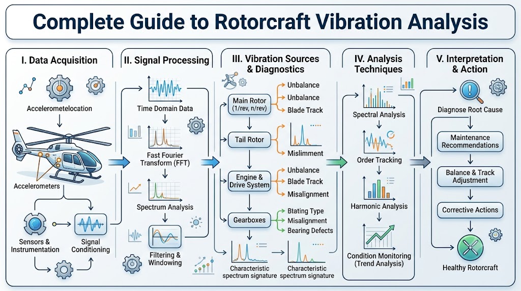
Rotorcraft vibration is an important consideration in helicopter operation, maintenance, and engineering. Because helicopters contain multiple rotating systems, vibration can originate from the main rotor, tail rotor, drivetrain, engine, accessories, or structural components.
Some vibration is inherent to rotorcraft design, but a new, changing, or abnormal vibration pattern can provide valuable diagnostic information. Vibration analysis helps maintenance professionals examine characteristics such as frequency, amplitude, phase, location, and trends to investigate potential sources.
This guide explains the fundamentals of rotorcraft vibration analysis, common vibration sources, measurement technologies, spectrum analysis, trend monitoring, troubleshooting concepts, and maintenance considerations.
Important: Aircraft-specific vibration limits, measurement procedures, rotor tracking and balancing methods, and corrective actions must come from applicable approved documentation and qualified rotorcraft maintenance personnel.
What Is Rotorcraft Vibration Analysis?
Rotorcraft vibration analysis is the process of collecting and interpreting vibration information from helicopter systems.
The analysis may examine characteristics such as:
- Frequency
- Amplitude
- Phase
- Direction
- Location
- Operating condition
- Changes over time
The purpose is to identify meaningful vibration patterns and investigate their possible sources.
Vibration analysis can support maintenance troubleshooting and condition monitoring, but it should not be treated as an independent substitute for physical inspection, approved maintenance procedures, or engineering evaluation.
Why Rotorcraft Vibration Analysis Matters
Helicopters contain numerous rotating and reciprocating components. These systems naturally generate mechanical forces that can be transmitted through the aircraft.
Vibration analysis can help maintenance teams:
- Investigate reported vibration
- Monitor component condition
- Establish baseline vibration behavior
- Identify changes over time
- Support troubleshooting
- Evaluate rotor-system behavior
- Monitor drivetrain components
- Support maintenance planning
- Improve understanding of recurring vibration patterns
The objective is not necessarily to eliminate every vibration.
Instead, the goal is to understand whether the observed vibration is expected, changing, or potentially abnormal for the particular aircraft and operating condition.
Why Helicopters Experience Vibration
Vibration is closely connected to the mechanical and aerodynamic characteristics of rotorcraft.
Common contributing sources include:
- Main rotor rotation
- Tail rotor rotation
- Rotor blade aerodynamic forces
- Rotor imbalance
- Blade tracking differences
- Gear rotation
- Gear meshing
- Shaft rotation
- Bearing behavior
- Engine operation
- Component wear
- Structural transmission
- Resonance
Because several rotating systems operate simultaneously, the vibration observed in one part of the aircraft may be influenced by another component.
This is one reason rotorcraft vibration analysis requires systematic interpretation rather than simply identifying the strongest vibration.
Major Sources of Rotorcraft Vibration
Main Rotor System
The main rotor is one of the most significant sources of helicopter vibration.
Potential contributors can include:
- Rotor blades
- Blade tracking
- Rotor head components
- Rotating assemblies
- Dynamic imbalance
- Component condition
A change in main-rotor vibration may require detailed analysis to determine whether the source is aerodynamic, mechanical, structural, or associated with another system.
Rotor tracking and balancing should always be performed using the aircraft manufacturer’s approved procedures and appropriate equipment.
Tail Rotor System
The tail rotor can also contribute to vibration.
Potential sources include:
- Tail rotor blades
- Blade condition
- Tracking
- Balance
- Rotor head components
- Tail rotor drive components
Because the tail rotor is connected to the drivetrain, vibration observed near the tail may require consideration of multiple systems rather than the rotor alone.
Drivetrain Vibration
The drivetrain transfers power through multiple rotating components.
Depending on the aircraft design, relevant components can include:
- Drive shafts
- Gearboxes
- Transmissions
- Bearings
- Couplings
- Gear sets
- Other rotating assemblies
Drivetrain vibration can produce identifiable patterns that may be useful during condition monitoring.
Potential concerns can include changes associated with:
- Gear meshing
- Bearing behavior
- Shaft rotation
- Component wear
- Alignment-related conditions
- Other mechanical changes
A vibration signature should not be treated as proof of a specific failure without appropriate supporting evidence.
Engine-Related Vibration
The engine can also contribute to helicopter vibration.
Potential sources may include:
- Rotating components
- Combustion-related behavior
- Engine mounting
- Accessories
- Engine-driven systems
Engine-related vibration should be considered alongside operating conditions and other available maintenance information.
A vibration measurement by itself generally does not establish the exact cause of an engine-related problem.
Airframe and Structural Vibration
Vibration can travel through the aircraft structure.
Possible transmission paths include:
- Frames
- Mounts
- Supports
- Panels
- Structural members
- Equipment mounts
A vibration that is generated by a rotating component can therefore become noticeable at a location that is not close to the original source.
This makes vibration location useful, but not necessarily conclusive.
Understanding Rotorcraft Vibration Frequency
Frequency describes how frequently a vibration event occurs.
In rotorcraft analysis, technicians may consider relationships involving:
- Rotational frequency
- Harmonics
- Blade-pass frequency
- Gear-mesh-related frequencies
- Engine-related frequencies
- Structural frequencies
Frequency information can help connect a measured vibration pattern with a particular rotating system or mechanical behavior.
For example, a vibration pattern associated with a rotating component may appear at a frequency related to that component’s operating speed.
However, frequency alone does not automatically identify a failure.
Aircraft configuration, operating condition, measurement location, and historical data all influence interpretation.
Understanding Vibration Amplitude
Amplitude represents the magnitude of vibration being measured.
Depending on the measurement system, vibration may be represented using different measurement methods and units.
Amplitude information can help show:
- Relative vibration severity
- Changes over time
- Differences between operating conditions
- Changes after approved maintenance actions
However, amplitude should not normally be considered in isolation.
A lower-amplitude vibration at a particular frequency can sometimes provide more useful diagnostic information than a larger but expected vibration component.
Aircraft-specific limits and interpretation criteria should always come from appropriate technical documentation.
Understanding Phase
Phase describes the timing relationship of a vibration signal relative to a reference.
Phase information can be useful when analyzing rotating systems because it can help technicians understand relationships between:
- Rotating components
- Vibration events
- Rotor behavior
- Dynamic imbalance
- Measurement locations
Phase becomes particularly useful when vibration analysis is combined with appropriate rotor tracking or balancing systems.
Detailed balancing calculations and adjustment procedures should be performed only by qualified personnel using approved aircraft-specific methods.
What Is a Vibration Signature?
A vibration signature is a characteristic pattern contained within vibration data.
A signature may include:
- Frequency
- Amplitude
- Phase
- Location
- Direction
- Operating condition
- Changes over time
A technician may compare a current vibration signature with historical measurements to determine whether the aircraft’s vibration behavior has changed.
This is one reason consistent measurement and good maintenance records are important.
Rotorcraft Vibration Measurement Equipment
Modern vibration analysis can use several types of equipment.
Accelerometers
Accelerometers measure vibration-related motion and can provide useful information for vibration analysis.
The appropriate sensor and installation depend on the aircraft and measurement system.
Vibration Sensors
Different sensors can be used to measure vibration at selected aircraft locations.
Sensor selection and placement must follow the applicable measurement procedure.
Tachometers
Rotational-speed information can provide an important reference for vibration analysis.
It can help establish relationships between vibration frequencies and rotating components.
Phase-Reference Sensors
Phase-reference systems provide timing information associated with rotating components.
This can support more advanced vibration analysis and rotor-system evaluation.
Data Acquisition Systems
Data acquisition equipment collects vibration signals for analysis.
Modern systems can capture multiple channels and operating parameters simultaneously.
Portable Vibration Analyzers
Portable analyzers can allow qualified personnel to collect and analyze vibration information during maintenance activities.
Their capabilities vary by system and application.
Rotor Track and Balance Systems
Specialized rotor track and balance systems can support rotor-system evaluation.
These systems may combine vibration measurements with rotational reference information.
They should be used according to the aircraft manufacturer’s procedures and equipment requirements.
How Vibration Data Is Collected
A typical vibration-monitoring process may involve several stages.
1. Identify the Aircraft and System
Confirm the aircraft, configuration, component, and reported vibration condition.
2. Select Appropriate Measurement Locations
Measurement points should be determined using the applicable maintenance or analysis procedure.
3. Use Appropriate Sensors
Sensors must be suitable for the measurement system and installed according to approved requirements.
4. Establish Relevant Operating Conditions
The measurement should be associated with the operating conditions under which the vibration is being evaluated.
5. Record Vibration Data
Collect the appropriate vibration information.
6. Record Supporting Information
Document relevant aircraft configuration, operating conditions, maintenance history, and other useful information.
7. Compare With Appropriate References
Review applicable limits, baselines, historical measurements, and maintenance information.
8. Analyze Trends
Determine whether the vibration is stable, changing, or showing a meaningful pattern.
The exact data-collection procedure varies by aircraft and should follow approved documentation.
Vibration Spectrum Analysis
A vibration spectrum shows vibration information across a range of frequencies.
Technicians may examine:
- Dominant frequency peaks
- Harmonics
- Broadband vibration
- Changes in peak amplitude
- Relationships between frequencies
Spectrum analysis can help narrow the range of possible sources.
For example, if a vibration peak is associated with a known rotating system, that information may help focus further investigation.
However, a single spectral peak does not automatically prove a particular component has failed.
Interpretation requires context.
Time-Domain and Frequency-Domain Analysis
Different forms of vibration analysis provide different types of information.
| Analysis Type | What It Shows | Typical Value |
|---|---|---|
| Time-domain | Vibration behavior over time | Useful for transient or repeating patterns |
| Frequency-domain | Vibration components by frequency | Useful for identifying frequency relationships |
| Phase analysis | Timing relationship to a reference | Useful for rotating-system analysis |
| Trend analysis | Changes over multiple measurements | Useful for condition monitoring |
Using multiple forms of information can provide a more complete picture than relying on one measurement alone.
Rotor Tracking and Dynamic Balancing
Rotor tracking and dynamic balancing are closely related to rotorcraft vibration management.
Rotor Tracking
Rotor tracking concerns the relationship between the paths followed by rotor blades.
Differences in blade tracking can contribute to vibration and may require appropriate maintenance attention.
Dynamic Balancing
Dynamic balancing addresses the distribution of rotating mass and associated vibration behavior.
Modern systems may use vibration and phase information to help qualified technicians evaluate rotor-system behavior.
However, rotor balancing is a specialized maintenance activity.
Balancing weights, adjustment sequences, blade changes, and flight-test procedures should never be improvised.
The applicable aircraft maintenance documentation and qualified personnel should determine the procedure.
Helicopter Drivetrain Vibration Analysis
Drivetrain vibration analysis is an important area of rotorcraft condition monitoring.
Technicians may examine vibration associated with:
- Gearboxes
- Transmissions
- Drive shafts
- Bearings
- Couplings
- Gear sets
Different components can produce different vibration characteristics.
For example, gear-related vibration may contain patterns associated with gear-mesh behavior, while bearing-related conditions may produce different frequency characteristics.
Trend monitoring can help identify changes that deserve additional investigation.
Vibration analysis should be combined with other approved inspection and maintenance methods rather than used as the sole basis for a maintenance decision.
Condition Monitoring and Trend Analysis
One vibration measurement provides a snapshot.
A series of measurements provides a trend.
Trend monitoring can help answer questions such as:
- Is vibration stable?
- Is it gradually increasing?
- Did it change after maintenance?
- Did the vibration pattern change?
- Is a particular frequency becoming more prominent?
For this reason, maintaining historical vibration data can be valuable.
Good trend data depends on consistent measurement methods and comparable operating conditions.
Rotorcraft Vibration Troubleshooting
Vibration troubleshooting should be systematic rather than based on assumptions.
Step 1: Confirm the Reported Symptom
Document what was observed and when it occurs.
Step 2: Review Recent Maintenance
Consider whether components were recently replaced, adjusted, inspected, or otherwise serviced.
Step 3: Examine Vibration Characteristics
Review available information about:
- Frequency
- Amplitude
- Phase
- Location
- Operating condition
Step 4: Compare Historical Data
Determine whether the condition is new or represents a change from the established baseline.
Step 5: Consider Relevant Systems
Potential sources may include:
- Main rotor
- Tail rotor
- Drivetrain
- Engine
- Airframe
- Accessories
Step 6: Consult Approved Documentation
Aircraft-specific documentation should guide further investigation.
Step 7: Conduct Qualified Inspection
Appropriately qualified personnel should perform required inspection and maintenance activities.
Step 8: Verify the Result
Following approved corrective action, appropriate personnel should confirm whether the vibration behavior has changed as expected.
Common Rotorcraft Vibration Problems
Rotorcraft vibration can be associated with many different conditions.
Potential categories include:
Rotor Imbalance
Changes in mass distribution can affect rotating-system behavior.
Blade Tracking Differences
Differences in blade tracking can contribute to vibration.
Component Wear
Mechanical wear can change the behavior of rotating systems.
Bearing-Related Conditions
Bearing condition can influence vibration characteristics.
Drivetrain Issues
Gears, shafts, couplings, and transmissions can generate vibration patterns.
Engine-Related Conditions
Engine operation and rotating components can contribute to vibration.
Structural Resonance
Certain structures can respond strongly to excitation at particular frequencies.
Loose or Deteriorated Components
Changes in component condition can alter vibration transmission.
These are broad categories rather than diagnoses. Actual fault identification requires aircraft-specific information and qualified analysis.
Vibration and Resonance
Resonance occurs when an excitation force interacts strongly with a system’s natural frequency.
In simple terms, a structure can respond more strongly when it is excited at or near a frequency at which it naturally tends to vibrate.
Rotorcraft contain numerous:
- Rotating systems
- Structural components
- Mounts
- Supports
- Mechanical assemblies
As a result, resonance can be an important consideration when investigating unusual vibration.
Resonance-related conditions require appropriate engineering and maintenance evaluation.
Common Rotorcraft Vibration Analysis Mistakes
1. Treating Every Vibration as the Same
Different vibration patterns can have different causes.
Better approach: Examine frequency, amplitude, phase, location, and operating conditions together.
2. Looking Only at Amplitude
A vibration magnitude by itself may not identify the source.
Better approach: Consider the complete vibration signature.
3. Ignoring Frequency
Frequency can provide valuable information about rotating systems.
Better approach: Examine the relationship between measured frequencies and relevant aircraft systems.
4. Ignoring Phase
Phase information can be valuable in rotating-system analysis.
Better approach: Use appropriate phase information when the analysis system and procedure require it.
5. Failing to Compare Historical Data
A single measurement may not show whether vibration behavior is changing.
Better approach: Compare current measurements with reliable historical data when available.
6. Using Inconsistent Measurement Conditions
Differences in measurement setup can make comparisons less meaningful.
Better approach: Follow consistent, approved measurement methods.
7. Installing Sensors Incorrectly
Poor sensor installation can affect data quality.
Better approach: Follow the applicable sensor and measurement procedure.
8. Assuming One Source Without Enough Evidence
A vibration near a component does not necessarily mean that component is the source.
Better approach: Consider transmission paths and supporting data.
9. Ignoring Recent Maintenance
A change after maintenance may provide useful context.
Better approach: Review maintenance history as part of the investigation.
10. Failing to Consult Approved Documentation
General vibration knowledge cannot replace aircraft-specific requirements.
Better approach: Use the applicable aircraft maintenance information.
11. Treating Software Output as a Final Diagnosis
Automated analysis can assist technicians but does not eliminate the need for professional interpretation.
Better approach: Combine software results with maintenance knowledge and aircraft-specific documentation.
12. Continuing Operation Despite Unexplained Abnormal Vibration
A new or significantly changing vibration should not simply be dismissed.
Better approach: Follow the applicable aircraft procedures and involve qualified personnel.
Vibration Analysis vs. Traditional Inspection
| Factor | Vibration Analysis | Traditional Inspection |
|---|---|---|
| Primary focus | Dynamic behavior | Physical condition |
| Information type | Measured vibration data | Visual, dimensional, or physical findings |
| Trend monitoring | Strong capability | Depends on inspection records |
| Diagnostic value | Can identify patterns | Can identify physical defects |
| Component visibility | Often indirect | Can provide direct physical evidence |
| Limitations | Requires proper data and interpretation | Some internal or dynamic conditions may not be obvious |
| Best use | Condition monitoring and diagnostic support | Physical evaluation and maintenance verification |
These approaches should generally be considered complementary rather than competing methods.
Technology in Modern Rotorcraft Vibration Monitoring
Vibration monitoring continues to benefit from improvements in digital measurement and data analysis.
Modern systems can include:
- Digital vibration analyzers
- Automated data collection
- Multi-channel sensors
- Condition-monitoring systems
- Trend dashboards
- Data-storage systems
- Remote analysis capabilities
- Predictive maintenance concepts
These technologies can make it easier to collect, organize, and compare vibration information.
However, technology does not eliminate the need for proper procedures and qualified interpretation.
Building a Rotorcraft Vibration Monitoring Program
A structured vibration-monitoring program can include several elements.
Establish a Baseline
Collect reliable measurements that represent the aircraft’s expected vibration behavior.
Define Measurement Procedures
Use consistent procedures appropriate for the aircraft.
Record Aircraft Configuration
Configuration changes can affect vibration behavior.
Record Operating Conditions
Measurements are more useful when their operating context is known.
Maintain Historical Records
Preserve previous measurements for comparison.
Establish Appropriate Alert Criteria
Use aircraft-specific approved information rather than generic vibration limits.
Monitor Trends
Look for meaningful changes rather than isolated differences.
Investigate Changes
Significant changes should receive appropriate attention.
Document Corrective Actions
Record relevant maintenance and follow-up information.
Verify Results
After approved maintenance, compare appropriate measurements to determine whether the vibration behavior has changed.
Questions to Ask When Investigating Rotorcraft Vibration
When a vibration concern is reported, useful questions may include:
- When was the vibration first noticed?
- Has its intensity changed?
- Under what operating conditions is it most noticeable?
- Is it associated with a particular part of the aircraft?
- Has recent maintenance been performed?
- Has a component recently been replaced?
- What does the vibration spectrum show?
- Is historical baseline data available?
- Are frequency and phase relationships known?
- What do the applicable maintenance documents specify?
- Has the aircraft been inspected by qualified personnel?
- Has the vibration changed following approved corrective action?
These questions help organize an investigation without assuming a particular fault.
Rotorcraft Vibration Analysis Checklist
Data Collection
- Aircraft identified
- Aircraft configuration documented
- Operating conditions recorded
- Measurement locations documented
- Sensor information recorded
- Measurement method documented
Analysis
- Frequency reviewed
- Amplitude reviewed
- Phase reviewed where applicable
- Historical trend reviewed
- Relevant systems considered
- Data quality assessed
Maintenance
- Applicable documentation consulted
- Qualified personnel involved
- Recent maintenance reviewed
- Findings documented
- Corrective actions recorded
- Results verified
Records
- Baseline data maintained
- Measurements archived
- Trends monitored
- Configuration changes documented
- Significant findings recorded
Decision Guide for Rotorcraft Vibration Analysis
If Vibration Is New
Treat the change as something requiring appropriate investigation rather than automatically assuming it is normal.
If Vibration Is Increasing
Review available trend data and follow the applicable aircraft maintenance procedures.
If the Source Is Unclear
Do not guess. Use qualified diagnostic resources and aircraft-specific documentation.
If Recent Maintenance Was Performed
Review the maintenance history as part of the investigation.
If Vibration Exceeds an Approved Limit
Follow the applicable aircraft maintenance instructions and involve qualified personnel.
If Data Is Inconsistent
Review measurement conditions, equipment, sensor setup, and data quality before drawing conclusions.
Frequently Asked Questions
Q1. What is rotorcraft vibration analysis?
Rotorcraft vibration analysis is the measurement and interpretation of vibration behavior in helicopter systems to support maintenance investigation, condition monitoring, and troubleshooting.
Q2. Why do helicopters experience vibration?
Helicopters contain rotating rotor systems, engines, gearboxes, shafts, and other mechanical components that naturally generate dynamic forces.
Q3. What are common sources of helicopter vibration?
Potential sources include the main rotor, tail rotor, drivetrain, engine, accessories, bearings, structural components, and other rotating systems.
Q4. What is a vibration signature?
A vibration signature is a pattern made up of characteristics such as frequency, amplitude, phase, location, and operating condition.
Q5. Why are frequency and amplitude important?
Frequency can help relate vibration to rotating or structural systems, while amplitude indicates the magnitude of the measured vibration. Both should be interpreted in context.
Q6. What is phase analysis?
Phase analysis examines the timing relationship between a vibration signal and an appropriate reference, which can be useful when evaluating rotating systems.
Q7. What equipment is used for rotorcraft vibration analysis?
Equipment may include accelerometers, vibration sensors, tachometers, phase-reference systems, data acquisition equipment, portable analyzers, and specialized rotor track and balance systems.
Q8. What is rotor tracking and balancing?
Rotor tracking evaluates blade-path relationships, while balancing addresses the distribution and dynamic behavior of a rotating assembly. Both require aircraft-specific procedures and qualified personnel.
Q9. Can vibration analysis identify mechanical problems?
It can provide valuable diagnostic information and identify patterns associated with potential problems, but vibration data alone does not always establish a specific failure.
Q10. How is vibration trend monitoring used?
Repeated measurements can be compared over time to identify changes in vibration behavior and support condition monitoring.
Q11. Is vibration analysis a replacement for physical inspection?
No. Vibration analysis and physical inspection provide different types of information and are generally complementary.
Q12. What should technicians do when unexplained vibration increases?
They should follow applicable aircraft procedures, review relevant data and maintenance history, and involve appropriately qualified personnel.
Q13. Why is historical vibration data important?
Historical data provides a baseline that can help identify meaningful changes in vibration behavior.
Q14. When should qualified maintenance personnel be involved?
Qualified personnel should be involved whenever vibration requires aircraft inspection, diagnosis, rotor adjustment, balancing, component evaluation, or corrective maintenance.
Conclusion
Rotorcraft vibration analysis provides valuable insight into the dynamic behavior of helicopter systems.
Frequency, amplitude, phase, location, and historical trends can help maintenance professionals investigate vibration conditions.
The most useful analysis combines reliable data with aircraft-specific documentation and maintenance knowledge.
Vibration monitoring can complement physical inspections and support proactive condition monitoring.
However, vibration signatures should not be treated as automatic diagnoses or substitutes for approved maintenance procedures.
For safe and reliable results, qualified personnel and aircraft-specific procedures should guide analysis, troubleshooting, and corrective action.

